LIST OF ILLUSTRATIONS Figure Page 1. Schematic of a Pressurized Water Reactor .............................. 3 2. Pressurized Water Reactor Core ....... 4 3. Control Rod of a Pressurized Water Reactor .............................. 5 4. Heat Exchangers ...................... 6 5. Pressurizer .......................... 7 6. Schematic of a Boiling Water Reactor .............................. 10 7. Control Rod .......................... 12 8. Recirculation System ................. 13 9. Steam Separators ..................... 14 10. Steam Dryer .......................... 14 11. PWR Emergency Core Cooling System .... 19 12. BWR Emergency Core Cooling System .... 21 LIST OF TABLES 1. Busbar Costs ......................... 24 2. Economic Data from Other Consortia ... 25 vi
ABSTRACT
Light water reactors are a category of nuclear power
reactor in which water is used as both a coolant and a
moderator. There are two types of light water
reactors: the pressurized water reactor and the
boiling water reactor. In a pressurized water reactor,
steam is produced in a secondary system. The main
components of a pressurized water reactor are the core,
control rods, reactor vessel, steam generators, and
pressurizer. The core contains fuel assemblies that
contain fuel rods filled with fuel pellets. The
coolant flows through the core where it is heated at
high pressure. Then coolant then flows to a series of
steam generators where the collant flows through the
heat exchangers and the steam drum. The pressure is
lowered and ateam is allowed to form which then flows
to a turbogenerator where electricity is produced. The
control rods control the amount of nuclear fission
reactions in the core while the pressurizer maintains
the operating pressure in the reactor coolant system.
The reactor vessel contains the fuel elements, the
control elements, and the core monitoring instruments.
In a boiling water reactor, steam is allowed to form
directly in the core. The main components of a boiling
water reactor are the core control rods, the core
shroud and reactor vessel, the recirculation system,
the steam separators, and the steam dryers. The core
of a boiling water reactor is slightly larger than that
of a pressurized water reactor but contains the same
elements. The coolant is circulated through the system
by the recirculation system that consists of two loops
containing pumps external to the reactor vessel and jet
pumps inside the vessel. After steam in formed in the
reactor vessel, it flows to a series of steam
separators where it is separated from the coolant. The
steam then flows through steam dryers where additional
drying is done, and then it proceeds to turn a
turbogenerator. The control rods and reactor vessel
function in the same way as in the pressurized water
reactor.
Safety system are designed to prevent meltdown in
both types of light water reactors. The safety systems
in a pressurized water reactor include the residual
heat removal system, the emergency core colling
vii
systems, and the containment building. The residual
heat removal system removes decay heat from the primary
coolant system during plant shutdown. The emergency
core cooling systems are designed to deal with loss-of-
coolant accidents. The passive system consists of
accumulators which inject coolant into the vessel when
an accident occurs. The low pressure injection systems
and the high pressure injection systems also provide
make-up water. The safety systems of a boiling water
reactor include the drywell and emergency core cooling
systems. The reactor core isolation cooling system
pumps water into the reactor during a loss-of-coolant
accident while the low and high pressure core spray
systems provide make-up water. The drywell encloses
the reactor vessel, and the containment vessel encloses
all the components of the reactor. The Nuclear
Regulatory Commission inspects all nuclear power plants
to ensure than these safety systems are adequate.
The economics of a nuclear power plant are
determined by the busbar cost and the operating
capacity costs. The busbar cost is determined by the
construction cost, the cost of operating and
maintaining the plant, and the cost of the fuel. The
operating capacity costs are determined by the
availability of fuel and the capacity of the plant.
viii
Report on
LIGHT WATER NUCLEAR REACTORS
I. INTRODUCTION
There are approximately five hundred nuclear power
plants in operation or under construction worldwide.
These plants can produce as much as 370,000 megawatts
of electricity. These nuclear power plants can be
categorized into four types: (1) light water reactors,
(2) heavy water reactors, (2) gas-cooled reactors, and
(4) breeder reactors. Basically, a nuclear power
reactor operates by having a central unit, called the
core, in which nuclear fission reactions take place and
produce heat. A liquid, called the coolant, flows
through the system and absorbs the heat produced in the
core. The liquid is then converted into steam that
drives a turbogenerator to produce electricity.
The purpose of this report is to present the basic
design, operation, and safety measures of light water
reactors to the city council. The city council is
currently investigating the possibility of membership
in a regional consortium as an alternative to increased
coal-fired production of electricity. This report will
explain how the two types of light water reactors, the
design to be used by the consortium, operate and
present the key safety and economic aspects of these
reactors. Although the operations of nuclear power
reactors does involve complex chemistry and physics,
these aspects of the discussion have been avoided; only
an introductory discussion of the mechanical operation
of the reactor will be presented.
The four parts of this report discuss (1) the design
and operation of pressurized water reactors, (2) the
design and operation of boiling water reactors,
(3) safety measures employed in these reactors, and (4)
economic aspects of these reactors' operation. The
sections on the two types of light water reactors will
describe the components and explain their operation.
The section on safety measures will discuss the causes
of meltdown, safety systems used in both types of
reactors, and the role of the Nuclear Regulatory
Commission plays to ensure the safety of these
reactors. The final section will review the various
costs involved in the construction and operation of a
nuclear power plant.
2
II. PRESSURIZED WATER REACTORS
This section of the report describes the key
components of the pressurized light water reactor and
explains their operation in the production of
electricity.
Description of the Major Parts
In a pressurized water reactor (see Figure 1),
the reactor cooling water entering the core is highly
pressurized so that it remains below the boiling point.
The water leaves the reactor to pass through steam
generators where a secondary coolant is allowed to boil
and produce steam to drive the turbine.
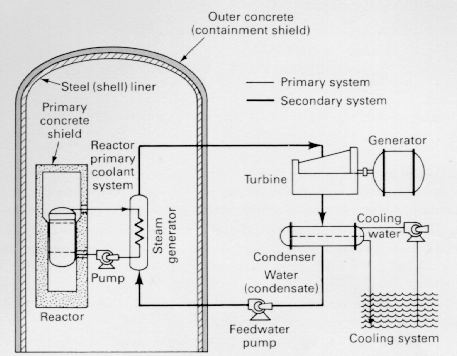
Figure 1. Schematic of a Pressurized Water
Reactor. Source: Nero, Anthony V. A Guidebook
to Nuclear Reactors, p. 78.
The key components in this process are the core, the
control rods, the reactor vessel, the steam generators,
and the pressurizer.
Core. The core is the active portion of the reactor
providing heat to the system. The core contains fuel
assemblies that contain fuel rods filled with fuel
pellets.
Fuel. The fuel in the pressurized water reactor
consists of cylindrical pellets of slightly enriched
uranium dioxide with a diameter of 0.325 in by 0.39 in.
The pellets are dished at the ends to allow for thermal
expansion (12:2004).
Fuel Rod. A fuel rod consists of a cylindrical
tube made of Zircalloy, a steel-gray alloy that highly
resistant to corrosion. This tube is 13 ft long with
an outer diameter of 0.39 in and a 0.025-in thich wall.
The tube is filled with fuel pellets and is sealed
(10:122).
Fuel Assembly. A fuel assembly is formed when
about 230 of the fuel rods are grouped in a bundle.
The fuel assembly is about 8 in on a side and 177 in
long (10:122). The reactor core is formed when about
240 of these assemblies are arranged in a cylindrical
array. These assemblies are supported between upper
and lower grid plates and are surrounded by a stainless
steel shroud. The grid plates consist of an assembly
of spring clips interlocked to form an egg-crate
arrangement providing rigid support and spacing of the
fuel rods (3:259).
Control Rods. Control rods provide a means of
changing the amount of heat produced in the core . . .
3
V. ECONOMIC ASPECTS
This section presents some of the key costs that
determine the economics of a nuclear power plant.
These costs will be compared to those associated with
other energy-producing systems, primarily those
involving coal. Costs are determined by the busbar
cost and the operating capacity costs.
Busbar Cost
The busbar cost is the total cost of electricity
leaving the power station. The busbar cost consists of
several factors: (1) construction cost, (2) operation
and maintenance costs, and (3) cost of the fuel. The
per-kilowatt cost of electricity estimated by the
Energy Research and Development Administration,
generated from 1000-megawatt nuclear, coal, and oil
plants beginning operation in 1980 is as follows:
Electricity costs (in mills*
Costs per kilowatt hour)
Nuclear Coal Oil
Capital costs 18.7 15.2 10.5
Fuel costs 5.8 13.7 25.7
Operation and
maintenance costs 2.8 3.3 2.2
TOTAL COSTS 27.3 32.2 38.4
* A mill is 1/10 of a cent ($0.001).
Table 1. Busbar Costs
Construction Cost. The construction costs include
the hardware, labor, original capital borrowed,
interest generated on that capital, and inflation of
capital costs. The construction costs for a nuclear
power plant are 18.7 mills per kilowatt hour, while
those of coal are 15.2 mills per kilowatt hour (8:20).
However, there is evidence to show that complete or
nearly complete nuclear power plants cost about twice
as much in real dollars than they do at the time they
are ordered (1:1). This inflation is the result of
additional quality assurance, inspection, and
24
documentation requirements. The rise in costs can also
be attributed to increases in the cost of engineering
manpower and of materials such as concrete, steel, and
wire (11:113). However, the actual cost of nuclear
steam supply system and the turbine generator together
amount to only 15% of the total cost (11:117). Most of
the cost of a nuclear plant can be attributed to
interest on capital during construction. Industry
experts hope that reducing the time between initial
plans for and operation of nuclear power plants will
cut these costs (8:23).
Operation and Maintenance Costs. The operation and
maintenance costs for a nuclear power plant are 2.8
mills per kilowatt hour compared to 3.3 mills per
kilowatt hour for a coal power plant. The difference
can be attributed to recent requirements for
installation of environmental protection scrubbing
equipment in coal plants. Another factor . . .
25
APPENDIX
INFORMATION SOURCES
1. Bupp, Irwin C., Jr., and Robert Trietel. 1976.
The Economics of Nuclear Power. Boston: MIT.
2. Burn, Duncan. 1978. Nuclear Power and the Energy
Crisis. New York: New York University Press.
3. Cameron, I.R. 1980. Nuclear Fission Reactors.
New York: McGraw-Hill.
4. Glasstone, Samuel and Alexander Sesonske. Nuclear
Reactor Engineering. Princeton, N.J.: D. Van
Nostrand.
5. Kessler, G. 1983. Nuclear Fission Reactors. New
York: Springer-Verlag Wien.
6. Lahey, R. T. and F. J. Moody. 1977. The Thermal-
Hydraulics of a Boiling Water Nuclear Reactor.
American Nuclear Society.
7. Murray, Raymond I. 1974. Nuclear Energy. New
York: Permagon.
8. Myers, Desaix III. 1977. THe Nuclear Power
Debate. New York: Praeger.
9. Naval Reactors Branch, Division of Reactor
Development, United States Atomic Energy
Commission. 1958. The Shippingport Pressurized
Water Reactor. Reading, Mass.: Addison Wesley.
10. Nero, Anthony V. 1979. A Guidebook to Nuclear
Reactors. Berkeley, Calif.: University of
California Press.
11. The Nuclear Energy Policy Study Group. 1977.
Nuclear Power Issues and Choices. Cambridge,
Mass.: Ballinger.
12. "Nuclear Reactor." 1980 ed. Van Nostrand's
Scientific Encyclopedia. Vol. 2.
13. Pickard, James K., ed. 1957. Nuclear Power
Reactors. Princeton, N.J.: D. Van Nostrand.
30
This information is owned and maintained by David A. McMurrey. For
information on use, customization, or copies, e-mail
davidm@austin.cc.tx.us or call (512) 476-4949.